
On this page I will describe my DTV colorfix, originally known as "The easy and better fix", but now widely known as the Spiff Lumafix or Spiff colorfix.
Originally I had this description on the same page as my more complicated fix, but it seems most people come here for the Spiff-fix, so I have moved the noise to a separate page. Also, since I have acquired a frame grabber, I have been able to make much nicer screen captures than the crappy pictures taken of the TV screen with a digital camera.
I have also done some work on trying to optimize the DTV palette to most closely resemble that of a real C64. There is hardly any difference between my findings and the palette that Zee optimized, but there are significant differences to the original DTV palette, so if possible, use either of these optimized palettes.
As described on Daniel Kahlin's Color Fix page, the video DACs on the DTV are faulty, presumably because the resistor values have been swapped.
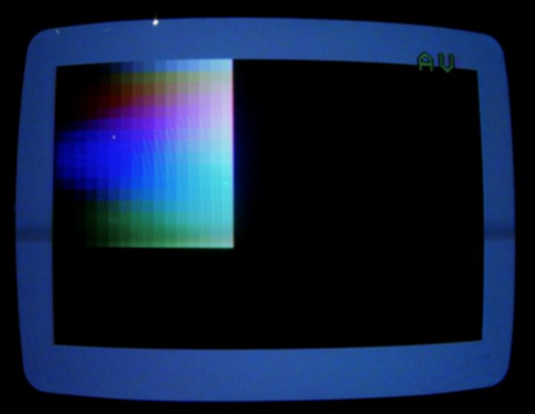
The image below shows the entire palette of the unmodified DTV (from TLR's displaytest.prg).
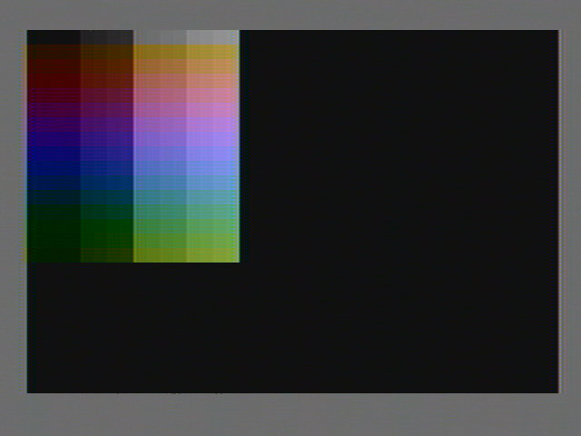
As seen on the image, the intensity (luma) has a very large step in the middle (the highest bit) and also somewhat large steps for the second highest bit. In essence the reason for this problem is the faulty design of the video DAC, where the resistor values in the R2R-network have been swapped, and a resistor to ground is missing.
I originally did a more complicated fix, but discussing the colorfix with Lars, we came to the conclusion that a simpler fix (replacing fewer resistors) was desirable. We came up with the idea of only replacing R16, R20 and R24, and adding RX. This would make the video DAC into the R2R-network as suggested, but at the same time make the values only half as big. Of course this means a heavier load on the ASIC outputs driving the DAC, but should also help us accomplish a higher white-level.
For the R2R-network to be optimal, a value of 165Ω was needed. This is certainly no standard value, but it was also considered easier to solder a second resistor in parallel to the ones already in the circuit. With the target of 165Ω (due to the 2R being 330Ω), and a 680Ω already there, a value of 217.9Ω in parallel would give the desired result. Using a 220Ω which is a standard E12 value would result in less than 1% error.
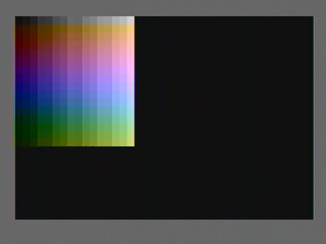
So 220Ω resistors were added in parallel with R16, R20 and R24. The results are shown below:
(Old picture is here)
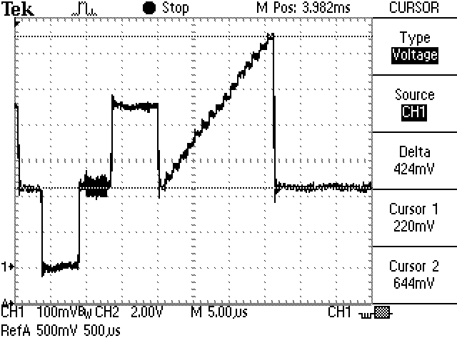
On the scope, the signal looks like this:
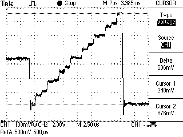
Clearly this is still not perfectly linear, but much better than the unmodified DTV. Also notice how the delta is now 636mV (compared to the nominal value of 700mV for a PAL signal), and indeed the white color on the palette is not as gray as with the previous fix. To get a more linear signal (and make a real R2R-network), the missing ground resistor (RX) was added. 330Ω was used, matching the other resistors in the R2R-network. The results are shown below:

(Old picture is here)
On this image we can see that the steps of the palette are more even. We can also see that the chroma (color) seems to work fine without modifications. We will return to that in a moment, but suffice it to say that there is really no reason to modify the chroma DAC.
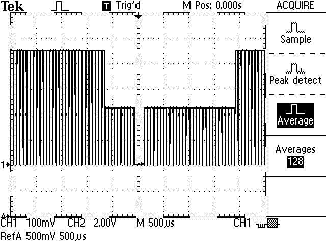
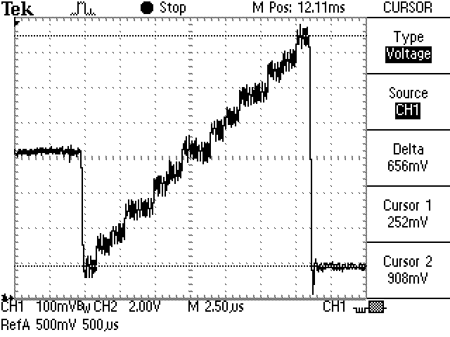
Looking at the scope picture confirms this:
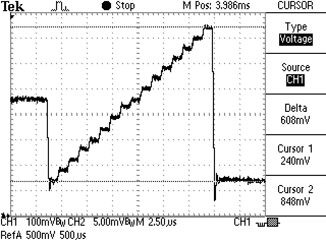
We can see a nice and linear stairway signal, as expected. Also notice how the delta is slightly lower (608mV) than before the pull-down resistor was added, but still significantly higher than both the unmodified DTV and the more comprehensive fix first tried. The result is a brighter white (although it is not too easy to see with my frame grabber).
All in all, this fix is simpler than the one previously described (requires only 4 added resistors, no de-soldering needed), and yet performs better (brighter white). Before we get on to the discussion of why there is no reason to fix the chroma, we can conclude that this simple fix is the way to go. To make it more clear, here is a schematic:
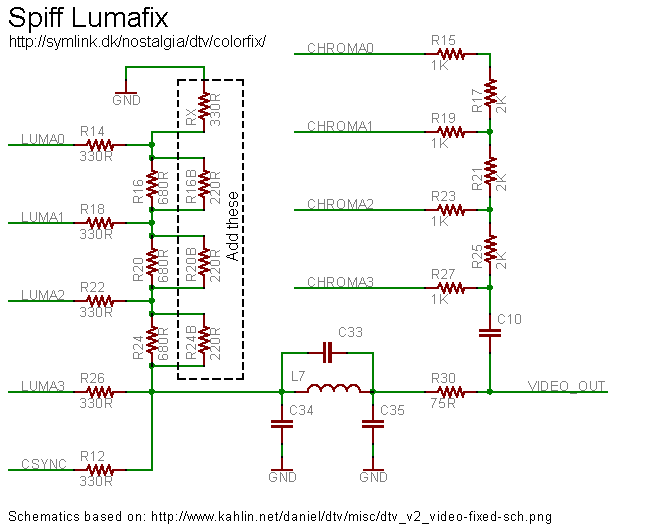
To sum it all up, simply add 220Ω resistors in parallel with R16, R20 and R24, and add a 330Ω resistor for RX (from the point between R14 and R16 to ground).
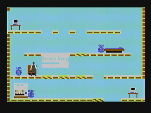
Finally, let's take a look at the improvements of Impossible Mission with the Spiff Lumafix:
(Old picture is here)
Compared to the first image, the improvement is huge. The intensity of the white color is much better now, which also helps setting it apart from the cyan text. The simple fix seems to perform very well, and even if you do not intend to add keyboard and IEC drive to your DTV, this simple color fix should be seriously considered, since it really makes the overall experience of the DTV much more nicer (and more like the original C64).
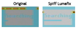
Here is a side-by-side comparison of the cyan text on white background in Impossible Mission:
As discussed, the Spiff Lumafix does not imply any modifications to the chroma DAC. The main reason for this is the fact that the amplitude of the chroma signal is not very important. Looking at the palettes above, we see that the first line is a grayscale (no chroma information), whereas the remaining lines all have full chroma.
Let's get a short explanation of how the composite video signal generated by the DTV works. The signal is called composite because it contains information about both the luma (intensity) and chroma (color). Let's start by looking at the signal levels. For PAL the blanking and black-levels are both 0V and the white-level is 700mV (nominally). The sync tip is -300mV, yielding a peak-to-peak voltage of 1V. The levels for NTSC are slightly different, but overall the semantics are the same.
To understand how the sync signal works, take a look at the following scope picture:
The image shows the vertical sync signal (in the middle of the image). The duration is about 3-4 scan-lines, where the signal is kept at the sync-level. The signal generated by the DTV is offset, so that the sync tip is 0V, and therefore both the black and white-levels are positive. This presumably does not matter due to the input on the TV being AC-coupled, and so any DC offset will not matter. This image was made with the first colorfix described above, and so the signal levels are not quite as high as specified in the standard.
Before and after the vertical sync pulse are the vertical blanking intervals. Notice how the signal is kept a the black-level, and after each scan-line drops to the sync-level for the horizontal sync pulse. The higher signal levels seen before and after is gray border of the palette program.
Now, if we look at each individual scan-line we see a similar composition:
We see the horizontal sync pulse on the left (with the back porch before that). This is followed by front porch, including the colorburst, which we will return to shortly, and then the actual video signal. On this picture, we see the (left) gray border followed by the ramp signal going from black to white (the first line of the palette). The signal then drops to the black level again (the black background after the palette). At the end of the scan-line (not shown on this image), the right part of the grey border comes, followed by the back porch, and then the next horizontal sync pulse, and the story repeats itself.
As we have already seen, the luma information (brightness) is encoded as the overall level of the signal, ranging from the black-level to the white-level. This allows us to create a monochrome (black and white) image, but how are the colors added?
In order to add color information to the existing TV signal, this had to be encoded at a higher frequency (4.43 MHz for PAL). Two differnt signals are needed for the color information, namely the hue (tone) and the saturation of the color. Let's start with the saturation, which is encoded as the amplitude of the high-frequency signal. Looking at the following scope-picture, which is the last scan-line of the palette, we can clearly see the color information imposed on the signal:
We can see that the amplitude of the imposed signal is constant over the entire scan-line (while the luma/intensity rises). In fact this is the case for all colors on the DTV, except the grayscales. This is also the reason why there are only two dimensions on the shown palettes: the saturation only has two levels, either off (yielding a gray color) or on (giving full color).
Now, the hue (or tone) of the color is encoded in an even more obscure way, as the phase difference between the color subcarrier and a reference signal. This reference signal is synchronized with the colorburst in the beginning of each scan-line, which is why the colorburst is needed. For PAL the reference signal (colorburst) alternates 180° for each line (PAL stands for Phase Alternation by Line), which gives more stable colors than NTSC, but for our explanation this makes no difference. The important part is that the color displayed on the screen is determined by the phase difference between the colorburst and the color subcarrier at a particular point of the signal.
So, returning to the issues of the faulty video DAC on the DTV we notice that the liniarity of the chroma DAC does not have much influence on the color. Ideally the chroma information should be a sine-wave, with the amplitude determining the saturation of the color (which for the DTV is either fully on of fully off). The color is determined by the phase difference, which is not affected by the non-liniarity of the chroma DAC.
If we take a look at the colorburst of the signal generated with the comprehensive fix described previously, it looks like this:
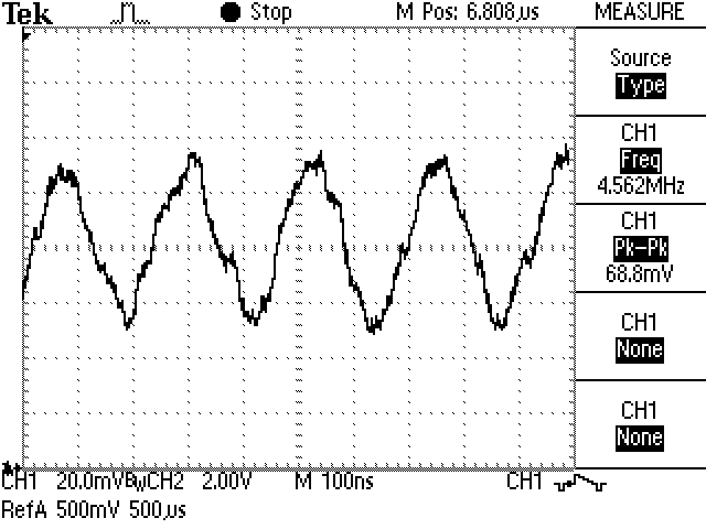
We notice that the signal looks more or less like a triangle-wave. It seems plausible that this is in fact how the signal is generated - by a counter counting up and down and outputting the 4 bits to the chroma DAC.
Now, if we take a look at the colorburst signal of the DTV that had the simpler colorfix (with no modifications to the chroma DAC):
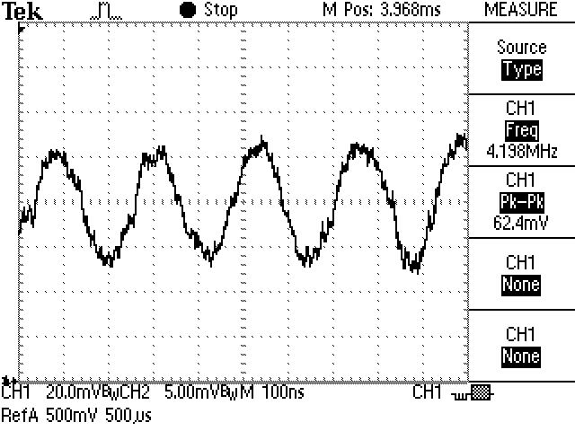
If anything, this looks like a slightly better attempt at a sine-wave. It seems the non-linearity of the original chroma DAC combined with the filtering by the capacitor C10 actually provides a better colorburst signal. We can therefore conclude that modifying the chroma DAC serves no purpose, and everyone is happy, since this also means fewer resistors need to be replaced.
 Electronics
 Nostalgia
 Projects
 Personal
 Links
Links